Login or Register for FREE!
Subelement E5
ELECTRICAL PRINCIPLES
Section E5C
Impedance plots and coordinate systems: plotting impedances in polar coordinates; rectangular coordinates
In polar coordinates, what is the impedance of a network consisting of a 100-ohm-reactance inductor in series with a 100-ohm resistor?
  • 121 ohms at an angle of 35 degrees
  • Correct Answer
    141 ohms at an angle of 45 degrees
  • 161 ohms at an angle of 55 degrees
  • 181 ohms at an angle of 65 degrees

Let’s take a look at an example. In polar coordinates, the impedance of a network consisting of a 100-ohm-reactance inductor in series with a 100-ohm resistor is 141 ohms at an angle of 45 degrees. (E5C01) In this example, x=100 and y=100, so

r = sqrt (X^2 + R^2) = sqrt ((100)(100) + (100)(100)) = sqrt (20000) = 141 ohms.

The cosine of the phase angle θ is equal to x/r, or 100/141, or .707. If you look up this value in a table of cosines, you’ll find that the angle is 45 degrees.

Here’s another thing to notice. When the value of the reactance is equal to the value of the resistance, the angle will be either 45 degrees or -45 degrees, depending on whether the net reactance is inductive or capacitive.

Note: Use the negative cosine

                                    OR

The impedances are in series and so we can add them (using vector arithmetic).

Ztotal squared = R squared + Xl squared = 100 squared + 100 squared = 20000

So Ztotal = square root (20000) = 141 ohms.

This is enough information to be able to select 141 ohms at 45 degrees as the correct answer.

As a double check we find the angle

Angle = INV tan (Xl/R) = INV tan(1) = 45 degrees.

So the impedance in polar notation is

141 ohms at 45 degrees.

Last edited by drichmond60. Register to edit

Tags: none

In polar coordinates, what is the impedance of a network consisting of a 100-ohm-reactance inductor, a 100-ohm-reactance capacitor, and a 100-ohm resistor, all connected in series?
  • 100 ohms at an angle of 90 degrees
  • 10 ohms at an angle of 0 degrees
  • 10 ohms at an angle of 90 degrees
  • Correct Answer
    100 ohms at an angle of 0 degrees

The 100 ohm reactance capacitor and 100 ohm reactance inductor have impedances which cancel each other leaving only the 100 ohm resistor providing an impedance. A resistance only impedance has a zero angle for the polar coordinates of the impedance and the impedance value is the same as for the resistor making 100 ohms at an angle of zero degrees.

Last edited by ad7gh. Register to edit

Tags: none

In polar coordinates, what is the impedance of a network consisting of a 300-ohm-reactance capacitor, a 600-ohm-reactance inductor, and a 400-ohm resistor, all connected in series?
  • Correct Answer
    500 ohms at an angle of 37 degrees
  • 900 ohms at an angle of 53 degrees
  • 400 ohms at an angle of 0 degrees
  • 1300 ohms at an angle of 180 degrees

r = sqrt (X^2 + R^2) = sqrt ((600 - 300)^2+ 400^2) = sqrt (250000) = 500 ohms

θ = arccos(x/r) = arccos(400/500) = 36.9 degrees or θ = arcsin(y/r) = arcsin((600 - 300)/500) = 36.9 degrees

Last edited by vaughanth. Register to edit

Tags: none

In polar coordinates, what is the impedance of a network consisting of a 400-ohm-reactance capacitor in series with a 300-ohm resistor?
  • 240 ohms at an angle of 36.9 degrees
  • 240 ohms at an angle of -36.9 degrees
  • 500 ohms at an angle of 53.1 degrees
  • Correct Answer
    500 ohms at an angle of -53.1 degrees

Phase angle = arctan ((XL - XC)/R)

Since there is no inductor the XL = 0.

arctan((0-400)/300) = arctan(-400/300) = arctan(-1.3...) = -53.1 degrees

Impedance is then calculated as |Z| = sqrt((XL-XC)^2+R^2)

sqrt((0-400)^2+300^2) = 500

Therefore it is 500 ohms at an angle of -53.1 degrees One can also answer this question without a calculator. When the 2 legs of the right triangle formed by the resistance and capacitance values, are 3x and 4x the hypotenuse has to be 5x (this is called a 3-4-5 triangle). So we know that the impedance has to be 500 ohms. Since the reactance is capacitive, we know that the angle has to be negative. 500 ohms at -53.1 degrees has to be the answer.

Last edited by ragove. Register to edit

Tags: none

In polar coordinates, what is the impedance of a network consisting of a 400-ohm-reactance inductor in parallel with a 300-ohm resistor?
  • Correct Answer
    240 ohms at an angle of 36.9 degrees
  • 240 ohms at an angle of -36.9 degrees
  • 500 ohms at an angle of 53.1 degrees
  • 500 ohms at an angle of -53.1 degrees

Note the reactances are in parallel not series The reactance from the resistor is ZR=300. The reactance from the inductor is ZL=400j (remember, inductive reactance is on the positive j axis.). Let Z be the total reactance. Since the reactances are in parallel, they sum reciprocally: 1/Z = 1/ZR+1/ZL = 1/300 +1/400j. So, taking the reciprocal we get Z=192 -144j. Converting to polar coordinates: |Z| = SQRT{192^2 +144^2]=240 and the phase angle is ArcTan(144/192)=36.9 degrees.

Recall, to take the reciprocal of 1/(a+bj) , multiply the numerator and denominator by a-bj and use j^2=-1.

Aded by KC6KID: My calculaion shows Z=192 + j144. The resulting complex impedance should be inductive, ie reactive part is positive

Last edited by kc6kid. Register to edit

Tags: none

In polar coordinates, what is the impedance of a network consisting of a 100-ohm-reactance capacitor in series with a 100-ohm resistor?
  • 121 ohms at an angle of -25 degrees
  • 191 ohms at an angle of -85 degrees
  • 161 ohms at an angle of -65 degrees
  • Correct Answer
    141 ohms at an angle of -45 degrees

Phase angle = arctan ((XL - XC)/R)

Since there is no inductor the XL = 0.

arctan((0-100)/100) = arctan(-100/100) = arctan(-1) = -45 degrees

Impedance is then calculated as |Z| = sqrt((XL-XC)^2+R^2)

sqrt((0-100)^2+100^2) = 141.4 answer D

Last edited by vaughanth. Register to edit

Tags: none

In polar coordinates, what is the impedance of a network comprised of a 100-ohm-reactance capacitor in parallel with a 100-ohm resistor?
  • 31 ohms at an angle of -15 degrees
  • 51 ohms at an angle of -25 degrees
  • Correct Answer
    71 ohms at an angle of -45 degrees
  • 91 ohms at an angle of -65 degrees

(C). 71 ohms at an angle of -45 degrees

Required Information:

A Capacitive Reactance graph in Cartesian Form maps the top two quadrants to complex numbers. So all real capacitive values will be negative.

Total impedance in polar form is: Z = RC/sqrt(R^2+C^2) and angle of arctan(R/C)

Therefore:

Z = (100*100)/sqrt(100^2+100^2) = 70.71

theta = arctan(100/100) = 45. But because real numbers must be in the lower two quadrants we know it is -45

Last edited by kc7zax. Register to edit

Tags: none

In polar coordinates, what is the impedance of a network comprised of a 300-ohm-reactance inductor in series with a 400-ohm resistor?
  • 400 ohms at an angle of 27 degrees
  • Correct Answer
    500 ohms at an angle of 37 degrees
  • 500 ohms at an angle of 47 degrees
  • 700 ohms at an angle of 57 degrees

Let’s take a look at an example. In polar coordinates, the impedance of a network consisting of a 300-ohm-reactance inductor in series with a 400-ohm resistor is 500 ohms at an angle of 37 degrees. (E5C08) In this example, x=300 and y=400, so

r = sqrt (x^2 + y^2) = sqrt ((300)(300) + (400)(400)) = sqrt (250000) = 500 ohms.

The sine of the phase angle θ is equal to x/r, or 300/500, or 0.6000. If you look up this value in a table of sines, you’ll find that the angle is 37 degrees. I personally would use a calculator. OR The cosine of the phase angle θ is equal to y/r, or 400/500, or 0.8000. The arccos (0.8) == 37 degrees. Here’s another thing to notice. When the value of the reactance is equal to the value of the resistance, the angle will be either 45 degrees or -45 degrees, depending on whether the net reactance is inductive or capacitive.

Last edited by cryshalsing. Register to edit

Tags: none

When using rectangular coordinates to graph the impedance of a circuit, what does the horizontal axis represent?
  • Correct Answer
    Resistive component
  • Reactive component
  • The sum of the reactive and resistive components
  • The difference between the resistive and reactive components

On a rectangular coordinate graph, remember that the horizontal axis plots the resistive component and the vertical axis plots the reactive component.

Visual:

When laying horizontal, one is more resistive to get up

When standing vertical, one is more reactive to their surroundings

Last edited by ke0qft. Register to edit

Tags: none

When using rectangular coordinates to graph the impedance of a circuit, what does the vertical axis represent?
  • Resistive component
  • Correct Answer
    Reactive component
  • The sum of the reactive and resistive components
  • The difference between the resistive and reactive components

When using rectangular coordinates to graph the impedance of a circuit, the vertical axis represents the reactive component and the horizontal axis represents the resistive component.

Fun Hint: Vertical Y axis... getting a rise (up) out of someone is a reaction (Reactance). Horizontal X axis is dragging that someone who resists (Resistance).

Last edited by kd7bbc. Register to edit

Tags: none

What do the two numbers represent that are used to define a point on a graph using rectangular coordinates?
  • The magnitude and phase of the point
  • The sine and cosine values
  • Correct Answer
    The coordinate values along the horizontal and vertical axes
  • The tangent and cotangent values
This question does not yet have an explanation! Register to add one

Tags: none

If you plot the impedance of a circuit using the rectangular coordinate system and find the impedance point falls on the right side of the graph on the horizontal axis, what do you know about the circuit?
  • It has to be a direct current circuit
  • It contains resistance and capacitive reactance
  • It contains resistance and inductive reactance
  • Correct Answer
    It is equivalent to a pure resistance

The horizontal axis represents purely resistive values, so if your answer lies anywhere along this axis, the value is a pure resistance.

Last edited by boromir905. Register to edit

Tags: none

What coordinate system is often used to display the resistive, inductive, and/or capacitive reactance components of an impedance?
  • Maidenhead grid
  • Faraday grid
  • Elliptical coordinates
  • Correct Answer
    Rectangular coordinates
This question does not yet have an explanation! Register to add one

Tags: none

What coordinate system is often used to display the phase angle of a circuit containing resistance, inductive and/or capacitive reactance?
  • Maidenhead grid
  • Faraday grid
  • Elliptical coordinates
  • Correct Answer
    Polar coordinates

The Faraday Grid has to do with renewable energy. The Maidenhead Grid is a geo-location system used by Hams. Elliptical Coordinates are used in Chemistry and Quantum Physics. Polar Coordinates would be the only possible answer.

Last edited by dbrejda. Register to edit

Tags: none

In polar coordinates, what is the impedance of a circuit of 100 -j100 ohms impedance?
  • Correct Answer
    141 ohms at an angle of -45 degrees
  • 100 ohms at an angle of 45 degrees
  • 100 ohms at an angle of -45 degrees
  • 141 ohms at an angle of 45 degrees

To convert the rectangular value to polar coordinates get the first part by taking the square root of the sum of the squares of each of the rectangular coordinares:

√(1002 + -1002) = √20000 = 141.4Ω

Next, get the polar angle by taking the arctangent of the ratio of the j co-ordinate and the other: tan-1 (-100/100) = -45o

Since there's the chance of some rounding errors in the square root the nearest value in the answers is very close and correct: 141 ohms at angle of -45 degrees.

Last edited by ad7gh. Register to edit

Tags: none

In polar coordinates, what is the impedance of a circuit that has an admittance of 7.09 millisiemens at 45 degrees?
  • 5.03 E-06 ohms at an angle of 45 degrees
  • Correct Answer
    141 ohms at an angle of -45 degrees
  • 19,900 ohms at an angle of -45 degrees
  • 141 ohms at an angle of 45 degrees

1/(7.09e-3) =141. Don't overlook the milli. That is the reason for the "e-3" above. Without it you get 0.141 which is not correct!!

Note: Admittance is the opposite of resistance, with Siemens being the unit. Hence the 1/(7.09E-3), or (7.09E-3)^-1 if you prefer. The angle is a minus 45 degrees due to the value being a siemen that is opposite of resistance. If the answer was resistance instead of siemens, the angle would be a positive 45 degrees.

Admittance is the reciprocal of Impedance, (Siemens instead of Ohms). When you take the reciprocal, you switch the sign (positive to negative angle).

Last edited by hmkitto. Register to edit

Tags: none

In rectangular coordinates, what is the impedance of a circuit that has an admittance of 5 millisiemens at -30 degrees?
  • 173 - j100 ohms
  • 200 + j100 ohms
  • Correct Answer
    173 + j100 ohms
  • 200 - j100 ohms

Impedance is the reciprocal of admittance. In polar coordinates, the impedance is reciprocal of absolute admittance with the reversal of phase angle, making

Z = 1 / Y = (1 / 0.005 S) with angle -(-30°) = 200 at 30° Ω

The translation from polar coordinates to rectangular coordinates is

A at (θ) = Acos(θ) + jAsin(θ),

which in this case makes

200cos(30°) + j200sin(30°) = 173.2 + j100 Ω.

Last edited by nojiratz. Register to edit

Tags: none

In polar coordinates, what is the impedance of a series circuit consisting of a resistance of 4 ohms, an inductive reactance of 4 ohms, and a capacitive reactance of 1 ohm?
  • 6.4 ohms at an angle of 53 degrees
  • Correct Answer
    5 ohms at an angle of 37 degrees
  • 5 ohms at an angle of 45 degrees
  • 10 ohms at an angle of -51 degrees

In a series circuit the impedances simply add but since the impedance of a capacitor has a negative j value and the impedance of an inductor has a positive j value their values are opposite. So, the final rectangular coordinate impedance is (4, 4-1) = (4, 3)Ω.

To convert the rectangular value to polar coordinates get the first part by taking the square root of the sum of the squares of each of the rectangular coordinates:

sqrt(4^2 + 3^2) = sqrt(25) = 5Ω

Next, get the polar angle by taking the arctangent of the ratio of the j coordinate and the other: arctan(3/4) = 36.9 degrees

5 ohms at angle of 37 degrees.

Last edited by vaughanth. Register to edit

Tags: none

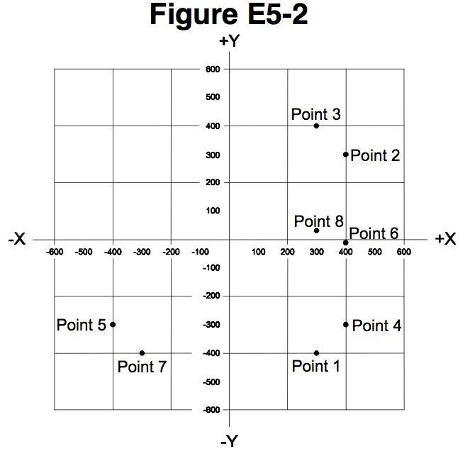
Which point on Figure E5-2 best represents that impedance of a series circuit consisting of a 400 ohm resistor and a 38 picofarad capacitor at 14 MHz?
  • Point 2
  • Correct Answer
    Point 4
  • Point 5
  • Point 6

The impedance of a capacitor, denoted by \(X_C\) is: \[X_C= \frac{1}{2\pi fC}\] where:

  • \(f\) is the frequency of interest
  • \(C\) is the capacitance in Farads.

The impedance of a capacitor has a negative j value. In the example shown we can mostly remove the large scale values by canceling the (\(10^{6}\)) of the MegaHertz and the (\(10^{-12}\)) of the picoFarads. So, we are left with (\(10^{-6}\)) giving an impedance value that is:

\begin{align} \frac{1}{2\pi\cdot14\cdot38\cdot10^{-6}}&\approx 299.2\:Ω\\ &\Rightarrow- j299.2\:Ω \end{align}

In a series circuit with a 400 Ω resistor the total impedance is \(400 - j299.2\:Ω\) which is in the lower right quadrant of the figure at about 400 in the +X direction and about 300 in the -Y direction.


Hint: Since this circuit is dealing with a capacitor (no inductor component), the capacitance magnitude will be negative. Only Point 4 is a negative capacitance. The pure resistance is 400, so that puts the point on 400.


Memory tip. If the frequency is 21 MHz or more, use the first number of the capacitor for the answer clue. If the frequency is less than 21 MHz, use the first number of the resistor for the answer clue.

Mnemonic: One rider is over two pedals (pi), two feet frequency), and two legs (L) or calves (C).

Last edited by dogshed. Register to edit

Tags: none

Which point in Figure E5-2 best represents the impedance of a series circuit consisting of a 300 ohm resistor and an 18 microhenry inductor at 3.505 MHz?
  • Point 1
  • Correct Answer
    Point 3
  • Point 7
  • Point 8

The impedance of the inductor \(Z_L = 2 \pi f L\), where:

  • \(f\) is the frequency of interest
  • \(L\) is the inductance in Henries.

The \(j\) value of the impedance of an inductor is positive.

\[Z_L = 2 \pi \times 3.505\text{ MHz} \times 18\ \mu\text{H}\]

Since the frequency here is in MegaHertz and the Inductance in microhenries, then the Mega (\(10^6\)) and micro (\(10^{-6}\)) exponents cancel:

\begin{align} Z_L &= 2 \pi \times 3.505\text{ MHz} \times 18\ \mu\text{H}\\ &= 2 \pi \times 3.505 \times 18\\ &= 396.4\ \Omega \end{align}

In a series circuit with a \(300\ \Omega\) resistor, the total impedance is \(300 + j396.4\ \Omega\) which is in the upper right quadrant of the figure at about \(300\) in the \(+x\) direction and about \(400\) in the \(+y\) direction, corresponding to Point 3 in Figure E5-2.

Test Tip: Because the resistance is \(300\ \Omega\), the only correct possibilities will be found at 300 ohms positive from the origin. Because the reactive component is only inductive, any correct possibility will be found relatively far away from the resistance axis in the positive direction. Point 3 is the only option that fits.

Memorization Tip: 3.505 mhz starts with the number 3, therefore, "Point 3" is the answer.

Last edited by knguyen553. Register to edit

Tags: none

Which point on Figure E5-2 best represents the impedance of a series circuit consisting of a 300 ohm resistor and a 19 picofarad capacitor at 21.200 MHz?
  • Correct Answer
    Point 1
  • Point 3
  • Point 7
  • Point 8

The impedance of a capacitor, denoted by \(X_C\) is: \[X_C= \frac{1}{2\pi fC}\] where:

  • \(f\) is the frequency of interest
  • \(C\) is the capacitance in Farads.

The impedance of a capacitor has a negative j value. In the example shown, we can mostly remove the large scale values by canceling the (106) of the MegaHertz and the (10-12) of the picoFarads. So, we are left with (10-6), giving an impedance value that is: \begin{align} X_C&= \frac{1}{2\pi (21.2\times 10^6 \text{ Hz})(19\times 10^{-12}\text{ F})} \\ &=\frac{1}{2\pi(21.2)(19)\left(10^{-6}\right)}\\ &\approx -j395.1\:\Omega \end{align}

In a series circuit with a 300 Ω resistor, the total impedance is \(300 - j395.1\:Ω\), which is in the lower right quadrant of the figure, at about 300 in the +X direction and about 400 in the -Y direction.


In short, since the problem only specifies a capacitance (and no inductance), only one answer falls on 300 Ω for the resistance (+X) axis and has a negative reactance: Point 1.

Also, seeing that the answer must be in the fourth quadrant, the only choices are Point 1 and Point 4, but only Point 1 is among the answer choices.

Last edited by marvsherman419. Register to edit

Tags: none

In rectangular coordinates, what is the impedance of a network consisting of a 10-microhenry inductor in series with a 40-ohm resistor at 500 MHz?
  • Correct Answer
    40 + j31,400
  • 40 - j31,400
  • 31,400 + j40
  • 31,400 - j40

When working with rectangular coordinates for impedance you will have two axes. A real and an imaginary axis. The imaginary axis is identified by the letter j as a standard.

The other thing to remember is that inductance is positive and capacitance is negative.

The resistor gives us the non-imaginary part of our answer and it needs no calculation, it is 40 and it is positive. That narrows us down to 40 + j31,400 or 40 - j31,400.

Since we only have an inductor to consider we know the imaginary portion should also be positive and we have narrowed it down to one answer.... 40 + j31,400


Wondering about the value \(31,400\) ?

Remember that the impedance of an inductor \(Z_L\) can be written as

\[ Z_L = 2\pi{f}L\]

Where:

\(f\) is the frequency of interest
\(L\) is the inductance in Henries.

So here, \begin{align} Z_L &= 2\pi{f}L\\ &= 2\pi \times 5\text{ MHz} \times 10\ \mu\text{H}\\ &\approx 31,400\ \Omega \end{align}

Last edited by qubit. Register to edit

Tags: none

Which point on Figure E5-2 best represents the impedance of a series circuit consisting of a 300-ohm resistor, a 0.64-microhenry inductor and an 85-picofarad capacitor at 24.900 MHz?
  • Point 1
  • Point 3
  • Point 5
  • Correct Answer
    Point 8

First, we know that the answer is going to be one of the three points that aligns horizontally at 300 ohms (the pure resistive component). Unfortunately, this only eliminates Point 5 as a possible answer, leaving us with Points 1, 3, and 8 as possibilities.

To determine which answer is correct, we need to compute the impedance of both the capacitor and inductor at the frequency given. We'll start with the impedance of the inductor: (Use the \(π\) key on your calculator for better accuracy.) \begin{align} X_L &= 2πfL\\ &= 2π\cdot(24.9\cdot10^6\text{ Hz}) \cdot (0.64\cdot10^{-6}\text{ H}) \\ &\approx 100.13 \:\Omega\ \end{align}

Then the impedance of the capacitor:

\begin{align} X_C &= \frac{1}{2πfC} \\ &= \frac{1}{2π\cdot(24.9 \cdot10^6 \text{ Hz}) \cdot (85\cdot10^{-12}\text{ F})} \\&= \frac{1}{0.0133} \\ &\approx 75.20\:\Omega \end{align}

This tells us that we have an inductive component (positive direction on the impedance axis) of approximately 100 \(\Omega\) and a capacitive component (negative direction on the impedance axis) of 75 \(\Omega\).

The resultant reactive component will be \(25\:\Omega\) of inductive impedance at the frequency given (\(X_L - X_C\approx 100-75=25\:\Omega\)).

This is a point slightly above the resistance axis in the positive direction. Only Point 8 satisfies that condition.

Test Tip: Because the resistance is \(300\ \Omega\), the only correct possibilities will be found at 300 ohms positive from the origin. Because the reactive component is relatively balanced, any correct possibility will be found relatively close to the resistance axis in the positive direction. Point 8 is the only option that fits.

Test "cheat": do the math to understand these Figure E5-2 problems, BUT for the test, the one's digit in the frequency names the point (14 MHz is Point 4), EXCEPT if the question involves BOTH inductance and capacitance you double that one's digit (2 x 4 = 8, so Point 8).

Last edited by k7kdg. Register to edit

Tags: none

Go to E5B Go to E5D