AMATEUR PRACTICES
Test equipment: analog and digital instruments; spectrum and network analyzers, antenna analyzers; oscilloscopes; RF measurements; computer aided measurements
Which of the following parameter determines the bandwidth of a digital or computer-based oscilloscope?
-
Input capacitance
-
Input impedance
-
Correct AnswerSampling rate
-
Sample resolution
This is a question where it is important to choose the "most correct" answer. In reality, the bandwidth of test equipment is limited by many factors.
However, one of the most important factors in a digital sampling oscilloscope is the sampling rate. Nyquist's sampling theorem states that a baseband signal can only be reconstructed unambiguously if the frequency components of the signal are under half of the sampling rate.
In other words, an oscilloscope sampling at 20 megasamples per second can unambiguously reconstruct a 10MHz signal. Above 10MHz, the frequencies "fold over" and appear the same as lower frequencies. Because of this, an oscilloscope sampling at 20MSPS is likely to have a filter that starts to roll off some time before 10MHz to reject the higher frequencies that cause aliasing.
Last edited by icee. Register to edit
Tags: arrl chapter 7 arrl module 7b
Which of the following parameters would a spectrum analyzer display on the vertical and horizontal axes?
-
RF amplitude and time
-
Correct AnswerRF amplitude and frequency
-
SWR and frequency
-
SWR and time
Envision an oscilloscope with a line going from left to right. The line going from left to right represents increments of frequencies. The line going up and down represents the strength (amplitude) of the sum of the signals present at the frequency. Most frequencies appear as spikes in compressed mode. Expand the line out, and the spikes appear as sharp mountains. This tool is useful in viewing frequencies close to the target frequency, bandwidths and RF shielding assessments.
Here is an example of a "spectrum scope", which is a type of spectrum analyzer display, along with the "waterfall display" under it: https://blog.icomamerica.com/wp-content/uploads/2020/04/VHFSpectrum_01.png
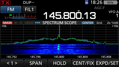
More info here: https://en.wikipedia.org/wiki/Spectrum_analyzer
Silly Hint: Single Asian Dad / Seeking Asian Female
Last edited by ko6hqx. Register to edit
Tags: arrl chapter 7
Which of the following test instrument is used to display spurious signals and/or intermodulation distortion products in an SSB transmitter?
-
A wattmeter
-
Correct AnswerA spectrum analyzer
-
A logic analyzer
-
A time-domain reflectometer
A spectrum analyzer displays the strength of a signal, and signals above and below the signal's frequency. Since spurious signals and/or intermodulation distortion products appear above and below a SSB signals frequency, the spectrum analyzer is a useful test instrument for displaying these.
You can adjust the vertical and horizontal scales on a spectrum analyzer - the vertical scale is the signal strength in Decibels, and the horizontal scale is the width of the spectrum being displayed.
Hint - The question asks about "spurious" signals and the answer is "spectrum" analyzer. Both words start with "sp".
Last edited by kwyatt. Register to edit
Tags: arrl chapter 7 arrl module 7b
What determines the upper frequency limit for a computer soundcard-based oscilloscope program?
-
Correct AnswerAnalog-to-digital conversion speed of the soundcard
-
Amount of memory on the soundcard
-
Q of the interface of the interface circuit
-
All of these choices are correct
Nyquist's sampling theorem states that the highest frequency that can be unambiguously reconstructed is half the sampling rate. Above this, higher frequencies "fold over" and are aliased as lower frequency signals.
Because of this, sound cards and other sampling systems generally have filters that reject higher frequencies that would cause aliasing.
Because of this, a soundcard sampling at 44,100 samples per second (a common sampling rate) can only reliably detect signals up to about 20KHz; but a 96KHz sample rate might allow the detection of signals at 40KHz or more.
Last edited by icee. Register to edit
Tags: arrl chapter 7 arrl module 7b
What might be an advantage of a digital vs an analog oscilloscope?
-
Automatic amplitude and frequency numerical readout
-
Storage of traces for future reference
-
Manipulation of time base after trace capture
-
Correct AnswerAll of these choices are correct
It might be helpful to consider that a digital oscilloscope is basically just a "computerized" oscilloscope -- it doesn't necessarily measure anything differently, it's just that there is a computer inside which can read, store, display, and manipulate all of the measurements.
Last edited by kd7bbc. Register to edit
Tags: arrl chapter 7 arrl module 7b
What is the effect of aliasing in a digital or computer-based oscilloscope?
-
Correct AnswerFalse signals are displayed
-
All signals will have a DC offset
-
Calibration of the vertical scale is no longer valid
-
False triggering occurs
Nyquist's sampling theorem states that the highest frequency that can be unambiguously reconstructed is at half the sampling rate, and above this, aliasing occurs.
If one should sample at 20MHz, signals of up to 10MHz can be reconstructed.
For example, if one supplied a 20,000,000 Hz signal to this oscilloscope, the oscilloscope would sample the same value every cycle, and the signal would totally disappear. If one instead supplied a 20,000,001Hz signal, the signal would drift in phase with the sampling at 1Hz, and a false 1Hz sine wave would be displayed.
Generally, an oscilloscope sampling at 20MHz will have filters to reject signals above 10MHz for this reason.
Memory Aid: When you read “aliasing” in the question, think of an alias as a false name. This will drive you toward the correct answer choice.
Last edited by samdypaulson. Register to edit
Tags: arrl chapter 7 arrl module 7b
Which of the following is an advantage of using an antenna analyzer compared to an SWR bridge to measure antenna SWR?
-
Antenna analyzers automatically tune your antenna for resonance
-
Correct AnswerAntenna analyzers do not need an external RF source
-
Antenna analyzers display a time-varying representation of the modulation envelope
-
All of these choices are correct
An antenna analyzer has its own built in signal source and can be connected directly to an antenna system to measure SWR. Whereas an SWR bridge needs to be used with a transmitter.
Hint: "Antenna analyzer" and "SWR" are in both the question and answer.
Last edited by gregor. Register to edit
Tags: arrl chapter 9 arrl module 9g
Which of the following instrument would be best for measuring the SWR of a beam antenna?
-
A spectrum analyzer
-
A Q meter
-
An ohmmeter
-
Correct AnswerAn antenna analyzer
An antenna analyzer is a piece of equipment that analyzes different aspects of an antenna. The specific capabilities vary between different analyzers, but one capability that all have in common is the ability to measure the Standing Wave Ratio, or SWR, of an antenna.
The SWR of an antenna is the simplest indicator of how well an antenna matches the transmitter system on a given frequency.
Last edited by wwward. Register to edit
Tags: arrl chapter 9 arrl module 9g
When using a computer's soundcard input to digitize signals, what is the highest frequency signal that can be digitized without aliasing?
-
The same as the sample rate
-
Correct AnswerOne-half the sample rate
-
One-tenth the sample rate
-
It depends on how the data is stored internally
Here's a relevant example:
https://en.wikipedia.org/wiki/Aliasing#Online_audio_example
The rule of thumb is to sample at a rate of double the highest frequency. Therefore, the highest frequency is half the sample rate.
Last edited by donate12. Register to edit
Tags: arrl chapter 7 arrl module 7b
Which of the following displays multiple digital signal states simultaneously?
-
Network analyzer
-
Bit error rate tester
-
Modulation monitor
-
Correct AnswerLogic analyzer
A logic analyzer is a device which captures and displays several digital signals at a time. Digital signals from a circuit are sampled and stored so that their states can then be displayed visually. This allows the user to analyze the timing relationships between different signals. Logic states are often displayed as wave forms or timing diagrams. Most logic analyzers can be set to trigger on a complex set of input conditions, and can decode many different communication protocols.
Last edited by n6sjd. Register to edit
Tags: arrl chapter 7 arrl module 7b
Which of the following is good practice when using an oscilloscope probe?
-
Correct AnswerKeep the signal ground connection of the probe as short as possible
-
Never use a high impedance probe to measure a low impedance circuit
-
Never use a DC-coupled probe to measure an AC circuit
-
All of these choices are correct
There are multiple potential issues with having a longer ground connection:
-
The scope is measuring the voltage differential between the ground and whatever you connect the probe to, so by keeping the ground short you minimize any voltage drop there may be.
-
The probe tip and ground of an oscilloscope acts like a sensitive antenna loop. The bigger the loop the more undesired signals or noise it will pick up. Also, the inductance of the ground wire increases with length, which can distort high-frequency signals. So, keep it short as possible.
Last edited by kd7bbc. Register to edit
Tags: arrl chapter 7 arrl module 7b
Which of the following procedures is an important precaution to follow when connecting a spectrum analyzer to a transmitter output?
-
Use high quality double shielded coaxial cables to reduce signal losses
-
Correct AnswerAttenuate the transmitter output going to the spectrum analyzer
-
Match the antenna to the load
-
All of these choices are correct
Transmitters normally put out enough power to radiate from an antenna; the signal thus produced is enough to travel to another antenna, potentially quite a distance away, and produce a signal in that antenna strong enough for a receiver to pick it up.
Spectrum Analyzers are generally intended to work with a receiver, or as a receiver with an antenna so if you transmit too much power into them you're likely to blow something up. Thus, to connect a spectrum analyzer to a transmitter output it is important to reduce (or attenuate) the transmitter output before it gets to the spectrum analyzer.
Hint: spectrum and transmitter are both in the question and correct answer.
Last edited by ldwyze. Register to edit
Tags: arrl chapter 7 arrl module 7b
How is the compensation of an oscilloscope probe typically adjusted?
-
Correct AnswerA square wave is displayed and the probe is adjusted until the horizontal portions of the displayed wave are as nearly flat as possible
-
A high frequency sine wave is displayed and the probe is adjusted for maximum amplitude
-
A frequency standard is displayed and the probe is adjusted until the deflection time is accurate
-
A DC voltage standard is displayed and the probe is adjusted until the displayed voltage is accurate
The probe is adjusted until the horizontal flats of a square wave are as flat as possible.
This adjustment is equivalent to making the probe have uniform attenuation over the range of frequencies to be measured. In passive probes this adjustment is usually a small adjustable capacitor.
"Understanding Probe Compensation: Probe compensation is the process whereby the probe capacitance is adjusted to compensate for the effects of the inherent input capacitance of the scope. A poorly compensated probe causes two main types of measurement inaccuracies. The first is incorrect amplitudes. The second is distorted waveforms, more specifically, changes in the rise and fall times of pulsed signals. These inaccuracies increase with increasing frequency."
https://www.rohde-schwarz.com/us/products/test-and-measurement/essentials-test-equipment/digital-oscilloscopes/understanding-probe-compensation_254520.html
Silly trick: Cubes are three dimensional, but squares are as flat as possible!
Last edited by gregor. Register to edit
Tags: arrl chapter 7 arrl module 7b
What is the purpose of the prescaler function on a frequency counter?
-
It amplifies low level signals for more accurate counting
-
It multiplies a higher frequency signal so a low-frequency counter can display the operating frequency
-
It prevents oscillation in a low-frequency counter circuit
-
Correct AnswerIt divides a higher frequency signal so a low-frequency counter can display the input frequency
A prescaler is an electronic counting circuit used to reduce a high frequency electrical signal to a lower frequency by integer division. The prescaler takes the basic timer clock frequency and divides it by some value before feeding it to the timer, according to how the prescaler register(s) are configured.
Mnemonic: think of -divisions- on a -scale-.
Silly Hint: the pre-schooler's (prescaler) voice has to be reduced to an acceptable range designated by the teacher (counter.)
Last edited by jrturnerbsn. Register to edit
Tags: arrl chapter 7 arrl module 7b
What is an advantage of a period-measuring frequency counter over a direct-count type?
-
It can run on battery power for remote measurements
-
It does not require an expensive high-precision time base
-
Correct AnswerIt provides improved resolution of low-frequency signals within a comparable time period
-
It can directly measure the modulation index of an FM transmitter
A direct-count frequency counter generally lets you select a gate time -- .1s, 1s, or 10 seconds-- and tells you the number of times the signal toggles in that time. In the case of a 10 second gate time, the resolution of the measurement is 1/10Hz.
For example, a 293.75Hz signal will toggle back and forth 2937 or 2938 times in 10 seconds, providing a measurement of 293.7 or 293.8 cycles per second (Hertz). The measurement takes 10 seconds.
A period measuring frequency counter can instead notice that the signal takes about 34.043 milliseconds to toggle back and forth 10 times, or 3.4043 ms/cycle. Inverting this yields 293.746 cycles per second-- a more accurate measurement accomplished in a much quicker time (a fraction of a second versus 10 seconds). This advantage is most pronounced with slow signals. As signals speed up, the accuracy and time resolution of the period measurement reduces the resolution of the frequency measurement.
Hint: Only the correct answer has the word "period"
Last edited by michaelv. Register to edit
Tags: arrl chapter 7 arrl module 7b
View Privacy Policy | Get help with HamStudy.org™