Electrical components: semiconductors; circuit diagrams; component functions
Component functions: rectification; switches; indicators; power supply components; resonant circuit; shielding; power transformers; integrated circuits
Which of the following devices or circuits changes an alternating current into a varying direct current signal?
-
Transformer
-
Correct AnswerRectifier
-
Amplifier
-
Reflector
A Rectifier is a component that uses diodes to direct all current down a specific path. There are different modes of rectification that will result in slightly different waveforms, but all of them take an alternating input current and output one that is direct. The wave will still be in the signal, but instead of varying from +140 to 0 to -140 and back, the signal will vary from +140 to 0 to +140 to 0, with all current flowing in the same direction. (the actual values may vary, this is just an example).
A transformer is a component that changes the voltage scale of a signal; it may convert from 5v to 10v, or from 110 to 12, etc. An amplifier is a component that amplifies (increases the magnitude of) a signal. A reflector is actually a part of an antenna, not a specific electrical component.
Last edited by kd7bbc. Register to edit
Tags: electrical components electronics ac power dc power arrl chapter 3 arrl module 6
What best describes a relay?
-
Correct AnswerA switch controlled by an electromagnet
-
A current controlled amplifier
-
An optical sensor
-
A pass transistor
Relays are used extensively in vehicles; whenever you flip a switch that causes something to happen it will most likely control a relay. A relay allows a fairly low power energy source to drive an electromagnet that closes a switch designed to handle a much higher energy source; for example, a relay may only need 100mA to drive a relay that can handle 10A. This is just an example, of course; actual values will vary.
Last edited by zazb. Register to edit
Tags: electrical components electronics arrl chapter 3 arrl module 6

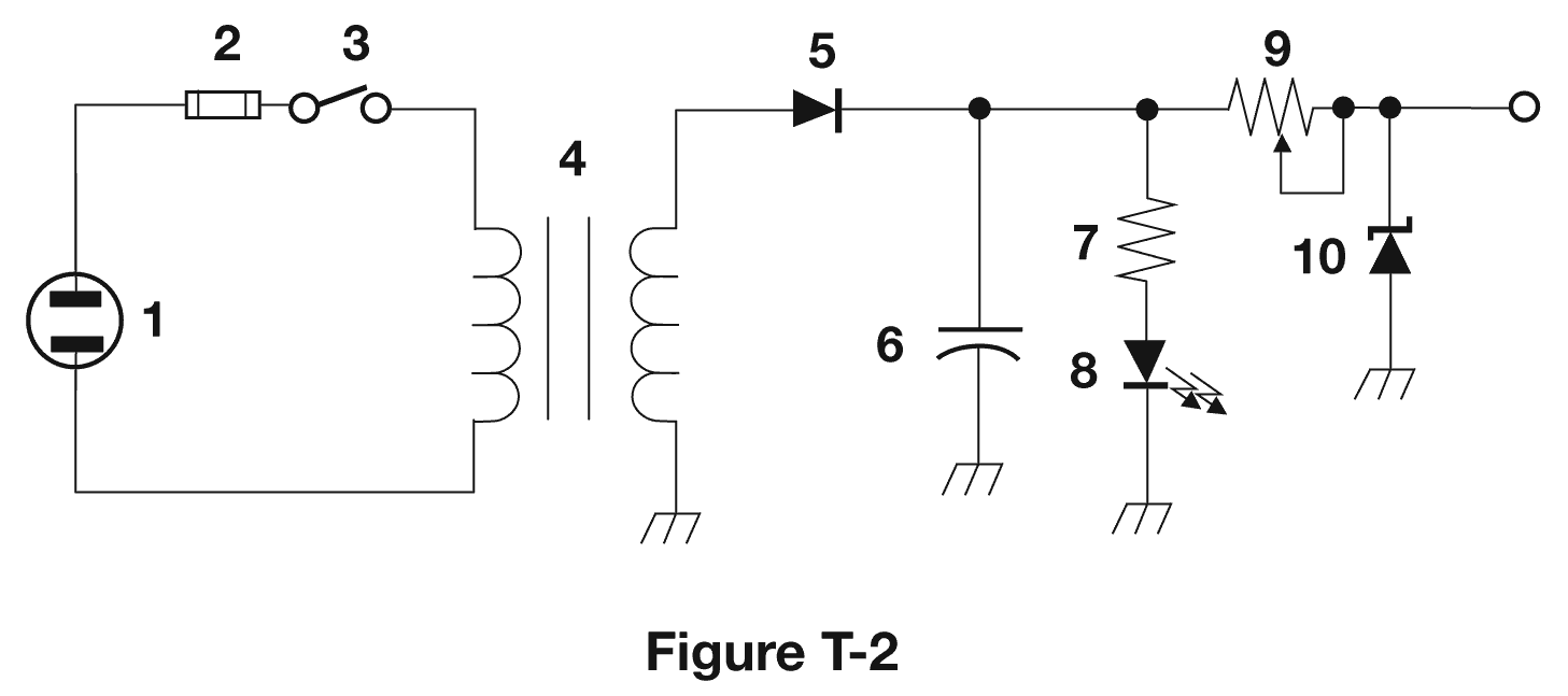
What type of switch is represented by component 3 in figure T2?
-
Correct AnswerSingle-pole single-throw
-
Single-pole double-throw
-
Double-pole single-throw
-
Double-pole double-throw
Single-pole means that there is a single set of contacts that are connected or disconnected with the switch. Note on the diagram that there is only a single line into the switch and a single line out. Double-pole would mean that the switch could connect or disconnect two wires at once and there would be two contacts going into the switch on the diagram.
Single-throw means that there is only one "choice" for each of those contacts; with a double-throw the switch would connect the input to one of two outputs. Triple-throw would be one of three outputs, etc
Last edited by kd7bbc. Register to edit
Tags: electrical components electronics diagram arrl chapter 3 arrl module 6
Which of the following can be used to display signal strength on a numeric scale?
-
Potentiometer
-
Transistor
-
Correct AnswerMeter
-
Relay
A Meter (in this case) is a device that measures something and displays the results on some form of numeric scale. A Signal Strength Meter is the type mentioned here, but other common types of meters include voltmeters, ohmmeters, ammeters, and thermometers.
A Potentiometer is a variable resistor, a transistor is an electrical gate that controls the flow of current along a path, and a relay is an electrically controlled switch. All three of the distractors are electrical components that affect the flow of electrons in a circuit. If you get this one wrong you should take a few minutes to review your basic electrical theory; you probably won't get it wrong more than once, however.
Last edited by kd7bbc. Register to edit
Tags: radio waves instruments arrl chapter 3 arrl module 6
What type of circuit controls the amount of voltage from a power supply?
-
Correct AnswerRegulator
-
Oscillator
-
Filter
-
Phase inverter
A regulator, more commonly referred to as a Voltage Regulator, regulates the voltage down to a particular point. The amount of current and what voltage the regulator targets depends on the type of regulator and sometimes depends on other components in the circuit.
The distractors don't regulate things:
oscillator - generates an electrical signal
filter - does signals processing, removing and/or enhancing frequency components in a signal
phase inverter - splits a signal to produce two outputs: one which is identical to the input, and one which is a mirror image (phase-inverted or flipped phase)
Last edited by glitteribbon. Register to edit
Tags: electrical components electronics dc power arrl chapter 5 arrl module 12
What component is commonly used to change 120V AC house current to a lower AC voltage for other uses?
-
Variable capacitor
-
Correct AnswerTransformer
-
Transistor
-
Diode
A "Transformer" is made up of two inductive coils wound around a ferrite core. The "Primary" coil is connected to the voltage source and the "Secondary" coil is connected to the circuit you are powering. The ratio of the number of turns on the primary coil to the secondary coil determines what the output voltage is.
For example, a 20 : 5 transformer fed 120V AC will produce a voltage of 30V AC on the secondary coil.
Last edited by calsamaus. Register to edit
Tags: electrical components electronics ac power arrl chapter 3 arrl module 6
Which of the following is commonly used as a visual indicator?
-
Correct AnswerLED
-
FET
-
Zener diode
-
Bipolar transistor
LED is an acronym for Light Emitting Diode. As the name suggests, this is a Diode (which only allows current in one direction) which produces light, making it a good choice for a visual indicator.
LEDs tend to have much lower power consumption than traditional "incandescent" or "fluorescent" bulbs used in your house.
Last edited by qubit. Register to edit
Tags: electrical components electronics arrl chapter 3 arrl module 6
Which of the following is used together with an inductor to make a tuned circuit?
-
Resistor
-
Zener diode
-
Potentiometer
-
Correct AnswerCapacitor
A "tuned circuit" is a common name for a resonant circuit made using an inductor (L) and a capacitor (C). This type of circuit is also known as an LC circuit. The use of the "L" is in honor of the Russian physicist Emil ("Heinrich") Khristianovich Lenz, who discovered Lenz's Law concerning the behavior of an induced current in a circuit.
https://en.wikipedia.org/wiki/LC_circuit
"C, I Tuned it." Capacitor + Inductor = Tuned Circuit.
Last edited by mk2019. Register to edit
Tags: capacitance inductance antenna arrl chapter 3 arrl module 6
What is the name of a device that combines several semiconductors and other components into one package?
-
Transducer
-
Multi-pole relay
-
Correct AnswerIntegrated circuit
-
Transformer
An integrated circuit, also known as an IC, is basically a microchip. These microchips have various components inside them, which means they contain one or more circuits inside, all integrated into a single package. A commonly known example of a complex integrated circuits would be the CPU of a computer, but these days just about any circuit board you look at will have "chips" on it, and those chips are all integrated circuits.
Last edited by kd7bbc. Register to edit
Tags: electrical components electronics arrl chapter 3 arrl module 6

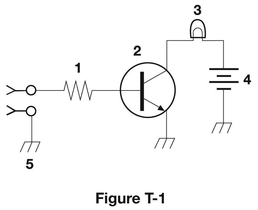
What is the function of component 2 in Figure T1?
-
Give off light when current flows through it
-
Supply electrical energy
-
Correct AnswerControl the flow of current
-
Convert electrical energy into radio waves
Figure 2 is an NPN-type bipolar junction transistor (the arrow points out, "Not Pointing IN"). Transistors (most commonly PNP or NPN type) have three terminals; two of them are part of one circuit, and the third (the one coming directly into the line) is a control input. Depending on what kind of transistor it is, applying current there will either allow current to flow across the other two legs or will restrict current from flowing.
Transistors definitely do not give off light; that's the Lamp, which is component #3. Component 4, a battery, supplies electrical energy, and nothing in this circuit converts electrical energy into radio waves.
Last edited by byfleischman. Register to edit
Tags: electrical components electronics transistors diagram arrl chapter 3 arrl module 6
What is a simple resonant or tuned circuit?
-
Correct AnswerAn inductor and a capacitor connected in series or parallel to form a filter
-
A type of voltage regulator
-
A resistor circuit used for reducing standing wave ratio
-
A circuit designed to provide high fidelity audio
Resonance occurs when the effects of capacitance and inductance in a circuit are the same (and opposite), for a given frequency. The only answer that mentions a capacitor and inductor is the right answer.
You always have to have capacitance and inductance to have resonance. So the answers about voltage regulation, SWR and high fidelity audio are wrong.
Last edited by k6yxh. Register to edit
Tags: arrl chapter 3 arrl module 6
Which of the following is a common reason to use shielded wire?
-
To decrease the resistance of DC power connections
-
To increase the current carrying capability of the wire
-
Correct AnswerTo prevent coupling of unwanted signals to or from the wire
-
To couple the wire to other signals
A layer of metal enveloping a wire functions as a Faraday cage, which prevents (or at least attenuates) the radio frequency energy being radiated to or from the wire. Thus, shielded wire minimizes distortion of not only its own signal conduction, but also that of any adjacent wire, as well.
Last edited by rccapps. Register to edit
Tags: arrl chapter 5 arrl module 12
View Privacy Policy | Get help with HamStudy.org™
