Login or Register for FREE!
Subelement E7
PRACTICAL CIRCUITS
Section E7B
Amplifiers: Class of operation; vacuum tube and solid-state circuits; distortion and intermodulation; spurious and parasitic suppression; microwave amplifiers
For what portion of a signal cycle does a Class AB amplifier operate?
  • Correct Answer
    More than 180 degrees but less than 360 degrees
  • Exactly 180 degrees
  • The entire cycle
  • Less than 180 degrees

As the name indicates, class AB amplifiers operate somewhere between class A and class B. Or perhaps the name is short for "Almost B" -- which would be true as well.

A class A amplifier operates at a full 360 degrees. The purity of amplification is terrific, but the efficiency is not.

Class B amplification uses two "finals", each operating for 180 degrees of the wave -- a great improvement in efficiency. However, with the introduction of bipolar transistors as finals, a problem with class B amplification developed. In a pure class-B configuration, there is a period of time where neither the forward-going nor the negative-going final has a forward-biased base-emitter junction. When this type of amplifier is fed a pure sine wave, there is a "hitch" at the zero crossing caused by neither final being forward-biased. This is called crossover distortion, and is a highly undesirable alteration of a pure sine wave.

Crossover
Distortion

The simple and elegant solution to this was to bias the finals so that each one operates slightly more than 180 degrees (but less than 360 degrees) to eliminate the problem of crossover distortion. The result is an amplifier with "Almost Class B" efficiency, but with distortion characteristics close to class A. Or, as it is called, Class AB.

Last edited by orochimaru. Register to edit

Tags: none

What is a Class D amplifier?
  • Correct Answer
    A type of amplifier that uses switching technology to achieve high efficiency
  • A low power amplifier using a differential amplifier for improved linearity
  • An amplifier using drift-mode FETs for high efficiency
  • A frequency doubling amplifier

Just remember that the key feature of Class D amplifiers is high efficiency.

Each one of the wrong answers misleads you by putting the letter D in the description: differential, drift-mode, and doubling.

Trick: Class D, D is for Digital -> Technology is the answer.

Last edited by phongn. Register to edit

Tags: none

Which of the following forms the output of a class D amplifier circuit?
  • Correct Answer
    A low-pass filter to remove switching signal components
  • A high-pass filter to compensate for low gain at low frequencies
  • A matched load resistor to prevent damage by switching transients
  • A temperature-compensated load resistor to improve linearity

A passive low-pass filter removes the unwanted high-frequency components, i.e., smoothes the pulses out and recovers the desired low-frequency signal. To maintain high efficiency, the filter is made with purely reactive components (inductors and capacitors), which store the excess energy until it is needed instead of converting some of it into heat.

Wikipedia.org - Class-D amplifier link: http://en.wikipedia.org/wiki/Class-D_amplifier

Silly memory tip: A “D” is a low pass grade.

Hint: The word "components" in question and only one answer stem.

Last edited by kd7bbc. Register to edit

Tags: none

Where on the load line of a Class A common emitter amplifier would bias normally be set?
  • Correct Answer
    Approximately half-way between saturation and cutoff
  • Where the load line intersects the voltage axis
  • At a point where the bias resistor equals the load resistor
  • At a point where the load line intersects the zero bias current curve

Setting the bias half-way between saturation and cutoff gives the maximum possible swing in collector voltage without entering either saturation or cut- off.

Last edited by orochimaru. Register to edit

Tags: none

What can be done to prevent unwanted oscillations in an RF power amplifier?
  • Tune the stage for maximum SWR
  • Tune both the input and output for maximum power
  • Correct Answer
    Install parasitic suppressors and/or neutralize the stage
  • Use a phase inverter in the output filter

to prevent unwanted oscillations you need to neutralize them.

Last edited by chevdor. Register to edit

Tags: none

Which of the following amplifier types reduces or eliminates even-order harmonics?
  • Push-push
  • Correct Answer
    Push-pull
  • Class C
  • Class AB

Symmetrical push–pull circuits must cancel even order harmonics, like f2, f4, f6 and therefore promote odd order harmonics, like (f1), f3, f5 when driven into the nonlinear range.

https://en.wikipedia.org/wiki/Push–pull_output

Last edited by chevdor. Register to edit

Tags: none

Which of the following is a likely result when a Class C amplifier is used to amplify a single-sideband phone signal?
  • Reduced intermodulation products
  • Increased overall intelligibility
  • Signal inversion
  • Correct Answer
    Signal distortion and excessive bandwidth

From Wikipedia: "Class-C amplifiers conduct less than 50% of the input signal and the distortion at the output is high". So, the option that mentions distortion is correct.

Silly hint: Class C - correct answer contains words starting with the next letters in the alphabet; signal distortion and excessive bandwidth. (c, d, &e).

Last edited by jaeger21. Register to edit

Tags: none

How can an RF power amplifier be neutralized?
  • By increasing the driving power
  • By reducing the driving power
  • Correct Answer
    By feeding a 180-degree out-of-phase portion of the output back to the input
  • By feeding an in-phase component of the output back to the input
This question does not yet have an explanation! Register to add one

Tags: none

Which of the following describes how the loading and tuning capacitors are to be adjusted when tuning a vacuum tube RF power amplifier that employs a pi-network output circuit?
  • The loading capacitor is set to maximum capacitance and the tuning capacitor is adjusted for minimum allowable plate current
  • The tuning capacitor is set to maximum capacitance and the loading capacitor is adjusted for minimum plate permissible current
  • The loading capacitor is adjusted to minimum plate current while alternately adjusting the tuning capacitor for maximum allowable plate current
  • Correct Answer
    The tuning capacitor is adjusted for minimum plate current, while the loading capacitor is adjusted for maximum permissible plate current

Most high-power amplifiers use vacuum tube technology. These amplifiers require that the operator tune the output circuit. The tuning capacitor is adjusted for minimum plate current and the loading capacitor is adjusted for maximum permissible plate current.

This is the correct procedure for adjusting the loading and tuning capacitors when tuning a vacuum tube RF power amplifier that employs a Pi-network output circuit.

Hint: There are only two choices with the word permissible. The wrong answer should be obvious because it doesn't make any sense.

Hint2: Be careful of maximum loading capacities

Last edited by kd7bbc. Register to edit

Tags: none

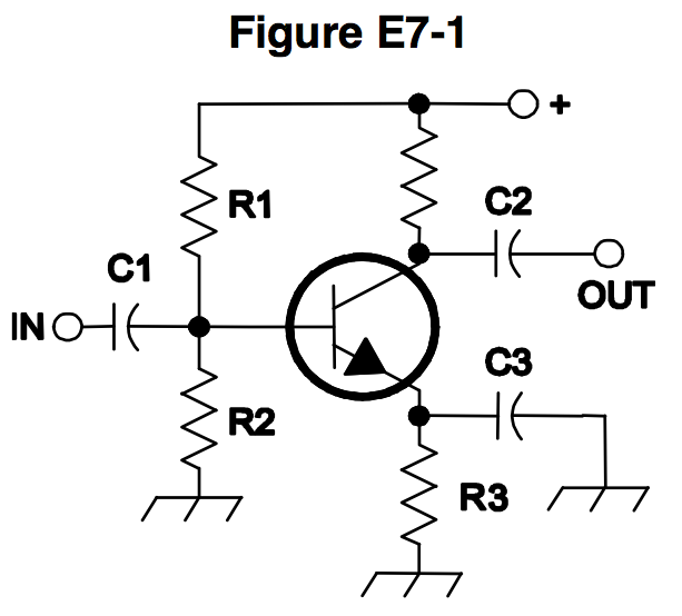
In Figure E7-1, what is the purpose of R1 and R2?
  • Load resistors
  • Correct Answer
    Fixed bias
  • Self bias
  • Feedback
This question does not yet have an explanation! Register to add one

Tags: none

In Figure E7-1, what is the purpose of R3?
  • Fixed bias
  • Emitter bypass
  • Output load resistor
  • Correct Answer
    Self bias
This question does not yet have an explanation! Register to add one

Tags: none

What type of circuit is shown in Figure E7-1?
  • Switching voltage regulator
  • Linear voltage regulator
  • Correct Answer
    Common emitter amplifier
  • Emitter follower amplifier
This question does not yet have an explanation! Register to add one

Tags: none

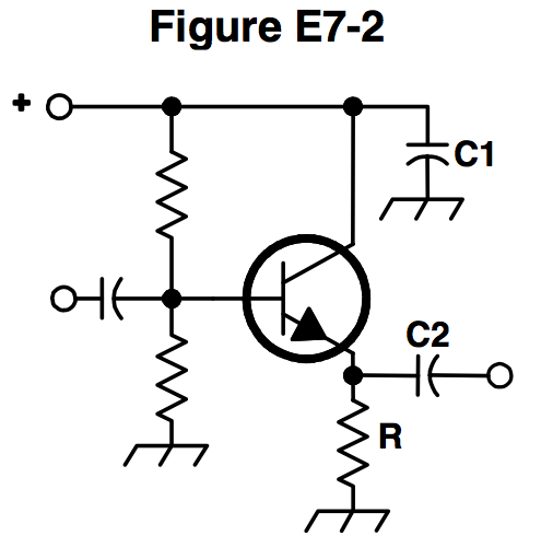
In Figure E7-2, what is the purpose of R?
  • Correct Answer
    Emitter load
  • Fixed bias
  • Collector load
  • Voltage regulation

This circuit is an Emitter Follower (also known as a Common Collector Amplifier).

It does not produce a voltage gain, but does offer significant current gain.

R provides a load for the emitter, and in so doing, also "lifts" the emitter far enough above ground so that a changing voltage that "follows" the base voltage can appear across it.

Last edited by orochimaru. Register to edit

Tags: none

In Figure E7-2, what is the purpose of C2?
  • Correct Answer
    Output coupling
  • Emitter bypass
  • Input coupling
  • Hum filtering
This question does not yet have an explanation! Register to add one

Tags: none

What is one way to prevent thermal runaway in a bipolar transistor amplifier?
  • Neutralization
  • Select transistors with high beta
  • Correct Answer
    Use a resistor in series with the emitter
  • All of these choices are correct

From Wikipedia:

Silicon shows a peculiar profile, in that its electrical resistance increases with temperature up to about 160 °C, then starts decreasing, and drops further when the melting point is reached. This can lead to thermal runaway phenomena within internal regions of the semiconductor junction; the resistance decreases in the regions which become heated above this threshold, allowing more current to flow through the overheated regions, in turn causing yet more heating in comparison with the surrounding regions, which leads to further temperature increase and resistance decrease. This leads to the phenomenon of current crowding and formation of current filaments (similar to current hogging, but within a single device), and is one of the underlying causes of many semiconductor junction failures.

Resistors limit current.

REMEMBER: We want to resist thermal runaway.

Last edited by kv0a. Register to edit

Tags: none

What is the effect of intermodulation products in a linear power amplifier?
  • Correct Answer
    Transmission of spurious signals
  • Creation of parasitic oscillations
  • Low efficiency
  • All of these choices are correct

Intermodulation products are third order products (or harmonics) that are caused by nonlinearities in amplification/mixing. As these signals are simply byproducts of amplification and are unintended, these signals are by definition spurious.

http://www.arrl.org/intermodulation

https://en.wikipedia.org/wiki/Intermodulation

Last edited by zapdawg. Register to edit

Tags: none

Why are third-order intermodulation distortion products of particular concern in linear power amplifiers?
  • Correct Answer
    Because they are relatively close in frequency to the desired signal
  • Because they are relatively far in frequency from the desired signal
  • Because they invert the sidebands causing distortion
  • Because they maintain the sidebands, thus causing multiple duplicate signals
This question does not yet have an explanation! Register to add one

Tags: none

Which of the following is a characteristic of a grounded-grid amplifier?
  • High power gain
  • High filament voltage
  • Correct Answer
    Low input impedance
  • Low bandwidth

Memory Aid: The ground is under your feet so it is low and won't impede your walk.


Compare to transistor base, collector, emitter. Which common lead type has low impedance? Which lead is like the grid in a vacuum tube?

Last edited by wileyj2956. Register to edit

Tags: none

What is a klystron?
  • A high speed multivibrator
  • An electron-coupled oscillator utilizing a pentode vacuum tube
  • An oscillator utilizing ceramic elements to achieve stability
  • Correct Answer
    A VHF, UHF, or microwave vacuum tube that uses velocity modulation

A klystron is a specialized linear-beam vacuum tube, invented in 1937 by American electrical engineers Russel and Sigurd Varian, which is used as an amplifier for high radio frequencies, from UHF up into the microwave range.

Source: Wikipedia - Klystron

Last edited by mvs90. Register to edit

Tags: none

What is a parametric amplifier?
  • A type of bipolar operational amplifier with excellent linearity derived from use of very high voltage on the collector
  • Correct Answer
    A low-noise VHF or UHF amplifier relying on varying reactance for amplification
  • A high power amplifier for HF application utilizing the Miller effect to increase gain
  • An audio push-pull amplifier using silicon carbide transistors for extremely low noise

Hint: "amplifier" and "amplification" are in the answer

Last edited by papusa. Register to edit

Tags: none

Which of the following devices is generally best suited for UHF or microwave power amplifier applications?
  • Correct Answer
    Field effect transistor
  • Nuvistor
  • Silicon controlled rectifier
  • Triac

[FET = Field Effect Transistor]

One advantage of the FET is its high gate to main current resistance, on the order of 100 MΩ or more, thus providing a high degree of isolation between control and flow. Because base current noise will increase with shaping time,[19] a FET typically produces less noise than a bipolar junction transistor (BJT), and is thus found in noise sensitive electronics such as tuners and low-noise amplifiers for VHF and satellite receivers. It is relatively immune to radiation. It exhibits no offset voltage at zero drain current and hence makes an excellent signal chopper. It typically has better thermal stability than a BJT.[3] Because they are controlled by gate charge, once the gate is closed or opened, there is no additional power draw, as there would be with a bipolar junction transistor or with non-latching relays in some states. This allows extremely low-power switching, which in turn allows greater miniaturization of circuits because heat dissipation needs are reduced compared to other types of switches.

per https://en.wikipedia.org/wiki/Field-effect_transistor

Last edited by mikerey. Register to edit

Tags: none

Go to E7A Go to E7C