Login or Register for FREE!
Subelement E7
PRACTICAL CIRCUITS
Section E7D
Power supplies and voltage regulators
What is one characteristic of a linear electronic voltage regulator?
  • It has a ramp voltage as its output
  • It eliminates the need for a pass transistor
  • The control element duty cycle is proportional to the line or load conditions
  • Correct Answer
    The conduction of a control element is varied to maintain a constant output voltage

HINT: voltage regulate = maintain voltage

In electronics, voltage regulators maintain a constant output voltage.

So, whether the question mentions Linear or Switching voltage regulators, choose the answer that mentions maintaining a constant output voltage.

The resistance of the regulator varies in accordance with the load resulting in a constant output voltage.

https://en.wikipedia.org/wiki/Linear_regulator

Last edited by kermitjr. Register to edit

Tags: none

What is one characteristic of a switching electronic voltage regulator?
  • The resistance of a control element is varied in direct proportion to the line voltage or load current
  • It is generally less efficient than a linear regulator
  • Correct Answer
    The control device's duty cycle is controlled to produce a constant average output voltage
  • It gives a ramp voltage at its output
This question does not yet have an explanation! Register to add one

Tags: none

What device is typically used as a stable reference voltage in a linear voltage regulator?
  • Correct Answer
    A Zener diode
  • A tunnel diode
  • An SCR
  • A varactor diode

A Zener diode is typically used as a stable reference voltage in a linear voltage regulator. When reverse biased, the diode breaks down and allows current to flow in the reverse direction when the voltage is above the avalanche point. The Zener voltage is the voltage necessary to cause the avalanche to occur and allow current to flow. As long as the reverse bias voltage remains above the avalanche point, the voltage drop across the Zener diode remains constant to provide a stable reference for regulating power supply output voltage.


Hint: this is a stretch but it worked for me...
stables are for horses
Zorro had a horse
Z is for Zener

A Zener Diode is the simplest type of voltage regulator.


Hint 2: a ZEE-ner is LEEnyer (linear). Weird, but helps me remember.


Remember seeing Varactor somewhere as an answer? Both hint 1 and 2 work as 'stable' and 'linear' are not a part of a different, similar question:

What type of semiconductor device is designed for use as a voltage-controlled capacitor? Varactor diode

Last edited by rkuhl. Register to edit

Tags: none

Which of the following types of linear voltage regulator usually make the most efficient use of the primary power source?
  • A series current source
  • Correct Answer
    A series regulator
  • A shunt regulator
  • A shunt current source
This question does not yet have an explanation! Register to add one

Tags: none

Which of the following types of linear voltage regulator places a constant load on the unregulated voltage source?
  • A constant current source
  • A series regulator
  • A shunt current source
  • Correct Answer
    A shunt regulator

An example of a shunt regulator is using a Zener diode in series with a resistor between supply and ground. The Zener diode establishes a constant voltage drop and the resistor sets a constant current.

Note: You can immediately dismiss two of the possible answers. "Regulator" appears in both the question and the answer.

HINT: While performing a carotid endarterectomy, (removing the blockage from the carotid artery), the surgeon must SHUNT the blood around the blockage to have CONSTANT blood flow to the brain.

Last edited by yr7 - extra. Register to edit

Tags: none

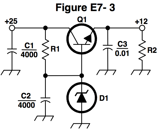
What is the purpose of Q1 in the circuit shown in Figure E7-3?
  • It provides negative feedback to improve regulation
  • It provides a constant load for the voltage source
  • Correct Answer
    It increases the current-handling capability of the regulator
  • It provides D1 with current
This question does not yet have an explanation! Register to add one

Tags: none

What is the purpose of C2 in the circuit shown in Figure E7-3?
  • Correct Answer
    It bypasses hum around D1
  • It is a brute force filter for the output
  • To self-resonate at the hum frequency
  • To provide fixed DC bias for Q1

If you see closely, C2 is connected in parallel to D1. This will basically act as a filter across D1 and prevent oscillations across D1 and hence prevent the hum.

Remember the term bypass capacitor and that a bypass capacitor will pass above certain wavelengths of AC current while blocking DC current. Bypass capacitors are very common for eliminating undesirable AC current such as noise so it is useful to remember this term.

Last edited by kv0a. Register to edit

Tags: none

What type of circuit is shown in Figure E7-3?
  • Switching voltage regulator
  • Grounded emitter amplifier
  • Correct Answer
    Linear voltage regulator
  • Emitter follower
This question does not yet have an explanation! Register to add one

Tags: none

What is the purpose of C1 in the circuit shown in Figure E7-3?
  • It resonates at the ripple frequency
  • It provides fixed bias for Q1
  • It decouples the output
  • Correct Answer
    It filters the supply voltage
This question does not yet have an explanation! Register to add one

Tags: none

What is the purpose of C3 in the circuit shown in Figure E7-3?
  • Correct Answer
    It prevents self-oscillation
  • It provides brute force filtering of the output
  • It provides fixed bias for Q1
  • It clips the peaks of the ripple
This question does not yet have an explanation! Register to add one

Tags: none

What is the purpose of R1 in the circuit shown in Figure E7-3?
  • It provides a constant load to the voltage source
  • It couples hum to D1
  • Correct Answer
    It supplies current to D1
  • It bypasses hum around D1
This question does not yet have an explanation! Register to add one

Tags: none

What is the purpose of R2 in the circuit shown in Figure E7-3?
  • It provides fixed bias for Q1
  • It provides fixed bias for D1
  • It decouples hum from D1
  • Correct Answer
    It provides a constant minimum load for Q1
This question does not yet have an explanation! Register to add one

Tags: none

What is the purpose of D1 in the circuit shown in Figure E7-3?
  • To provide line voltage stabilization
  • Correct Answer
    To provide a voltage reference
  • Peak clipping
  • Hum filtering

Component D1 is a zener diode and when reverse biased as shown and when the voltage equals or exceeds the zener diode specification the zener diode will maintain a constant voltage across it that is based on the zener diode model selected, assuming the source doesn't exceed the current limit of the zener (one purpose of R1). Thus, the zener diode creates a very effective reference voltage.

Last edited by ad7gh. Register to edit

Tags: none

What is one purpose of a "bleeder" resistor in a conventional (unregulated) power supply?
  • To cut down on waste heat generated by the power supply
  • To balance the low-voltage filament windings
  • Correct Answer
    To improve output voltage regulation
  • To boost the amount of output current

Hint: If you give blood and you're a "Bleeder" you have "improved output"

Last edited by papusa. Register to edit

Tags: none

What is the purpose of a "step-start" circuit in a high-voltage power supply?
  • To provide a dual-voltage output for reduced power applications
  • To compensate for variations of the incoming line voltage
  • To allow for remote control of the power supply
  • Correct Answer
    To allow the filter capacitors to charge gradually
This question does not yet have an explanation! Register to add one

Tags: none

When several electrolytic filter capacitors are connected in series to increase the operating voltage of a power supply filter circuit, why should resistors be connected across each capacitor?
  • To equalize, as much as possible, the voltage drop across each capacitor
  • To provide a safety bleeder to discharge the capacitors when the supply is off
  • To provide a minimum load current to reduce voltage excursions at light loads
  • Correct Answer
    All of these choices are correct
This question does not yet have an explanation! Register to add one

Tags: none

What is the primary reason that a high-frequency inverter type high-voltage power supply can be both less expensive and lighter in weight than a conventional power supply?
  • The inverter design does not require any output filtering
  • It uses a diode bridge rectifier for increased output
  • Correct Answer
    The high frequency inverter design uses much smaller transformers and filter components for an equivalent power output
  • It uses a large power-factor compensation capacitor to create "free power" from the unused portion of the AC cycle

Hint: smaller transformer and components = lighter and more often less expensive.

Last edited by jmsian. Register to edit

Tags: none

Go to E7C Go to E7E