ANTENNAS AND TRANSMISSION LINES
Matching: matching antennas to feed lines; phasing lines; power dividers
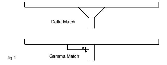
What system matches a higher impedance transmission line to a lower impedance antenna by connecting the line to the driven element in two places spaced a fraction of a wavelength each side of element center?
-
The gamma matching system
-
Correct AnswerThe delta matching system
-
The omega matching system
-
The stub matching system
Answer: The delta matching system
An easy way to remember this is the two lines help form a triangle, or the Greek letter used as the fourth letter in the phonetic alphabet - \(\Delta\).
For a visual representation between a delta and a gamma match, see: here
Hint: The question says 'higher' impedance. Think Delta planes fly 'higher'.
Hint: The Greek letter Delta is used to indicate "change" in math and science, and we're changing impedance in the system.
Last edited by kd7bbc. Register to edit
Tags: arrl chapter 9 arrl module 9e
What is the name of an antenna matching system that matches an unbalanced feed line to an antenna by feeding the driven element both at the center of the element and at a fraction of a wavelength to one side of center?
-
Correct AnswerThe gamma match
-
The delta match
-
The epsilon match
-
The stub match
A Gamma-match can match impedance below 50 ohms right up to that 50 ohms which your transceiver wants to see. A Yagi antenna almost never has an impedance of 50 ohms.
REF: http://www.dx-antennas.com/Gamma_match.htm
When a gamma match is used with a Yagi antenna, the driven element must be a single piece (not split in the middle) and can be mounted directly to the boom. It doesn't need to be insulated from the boom. This provides greater mechanical stability.
Silly Hint: Fraction starts with an F, which is one letter in the alphabet before G, which is the first letter in Gamma
Last edited by gregor. Register to edit
Tags: arrl chapter 9 arrl module 9e
What is the name of the matching system that uses a section of transmission line connected in parallel with the feed line at or near the feed point?
-
The gamma match
-
The delta match
-
The omega match
-
Correct AnswerThe stub match
Hint: A “SHORT length” = A “STUB.”
In microwave and radio-frequency engineering, a stub is a length of transmission line or waveguide that is connected at one end only. The free end of the stub is either left open-circuit or (especially in the case of waveguides) short-circuited. Neglecting transmission line losses, the input impedance of the stub is purely reactive; either capacitive or inductive, depending on the electrical length of the stub, and on whether it is open or short circuit. Stubs may thus be considered to be frequency-dependent capacitors and frequency-dependent inductors. Because stubs take on reactive properties as a function of their electrical length, stubs are most common in UHF or microwave circuits where the line lengths are more manageable. Stubs are commonly used in antenna impedance matching circuits and frequency selective filters.
http://en.wikipedia.org/wiki/Stub_(electronics)
Last edited by samdypaulson. Register to edit
Tags: arrl chapter 9 arrl module 9e
What is the purpose of the series capacitor in a gamma-type antenna matching network?
-
To provide DC isolation between the feed line and the antenna
-
Correct AnswerTo cancel the inductive reactance of the matching network
-
To provide a rejection notch that prevents the radiation of harmonics
-
To transform the antenna impedance to a higher value
The PVC insulation that encases the center conductor of a coaxial cable is within the outer tube that provides a series capacitance of some gamma-type matching networks.
The inductive reactance is cancelled by the series capacitance within the matching network. This will lead to a defined resonance.
Hint: "Matching Network" is in the answer.
Memory tip: The gamma match TV series was cancelled due to unwanted reactions (reactance).
Last edited by wadeshearer. Register to edit
Tags: arrl chapter 9 arrl module 9e
How must the driven element in a 3-element Yagi be tuned to use a hairpin matching system?
-
Correct AnswerThe driven element reactance must be capacitive
-
The driven element reactance must be inductive
-
The driven element resonance must be lower than the operating frequency
-
The driven element radiation resistance must be higher than the characteristic impedance of the transmission line
Think of the hairpin as a coil. It is a conductor with an inductive reactance. A tuned antenna is resonant which means inductive and capacitive reactances cancel each other out. For an inductor to tune an antenna the antenna must be capacitive.
Hint: Hairpin = Inductor, Inductors cancel Capacitors, to tune, we must have cancelled reactance. Thus The driven element reactance must be capacitive
Hint #2: Hairpin goes on your head. So does a baseball cap (Capacitive).
Silly hint: Reactance must be Capacitive so put a "Hairpin" in your "Cap"
Last edited by knguyen553. Register to edit
Tags: arrl chapter 9 arrl module 9e
What is the equivalent lumped-constant network for a hairpin matching system of a 3-element Yagi?
-
Pi-network
-
Pi-L-network
-
Correct AnswerA shunt inductor
-
A series capacitor
The equivalent lumped-constant network for a hairpin matching system of a 3-element Yagi is a shunt inductor.
Remember that the driven element must be capacitive. The hairpin matching system must be inductive. Hence, a shunt inductor is its equivalent.
Last edited by qubit. Register to edit
Tags: arrl chapter 9 arrl module 9e
What term best describes the interactions at the load end of a mismatched transmission line?
-
Characteristic impedance
-
Correct AnswerReflection coefficient
-
Velocity factor
-
Dielectric constant
The reflection coefficient, represented by the uppercase Greek letter gamma \(\Gamma\), is defined as
\[\Gamma = {(Z_L - Z_0) \over (Z_L + Z_0)}\]
where \(Z_L\) is the impedance of the load and \(Z_0\) is the characteristic impedance of the transmission line. If \(Z_0\) and \(Z_L\) are the same, the reflection coefficient (\(\Gamma\)) is zero. And the reflection coefficient increases the more \(Z_L\) and \(Z_0\) differ, indicating stronger mismatch between the load and transmission line.
The lowercase Greek letter rho \(\rho\) is often used instead of gamma.
Silly hint:the transmission line "reflected" on his behavior the day he lost Mrs Load
Hint: the lake had a "reflection" of the "line"
Last edited by gregor. Register to edit
Tags: arrl chapter 9 arrl module 9f
Which of the following measurements is characteristic of a mismatched transmission line?
-
An SWR less than 1:1
-
A reflection coefficient greater than 1
-
A dielectric constant greater than 1
-
Correct AnswerAn SWR greater than 1:1
Think of logic behind this problem. One ratio number must be higher than the other (it is the whole point of ratios). This is where SWR comes into play. SWR compares the impedance together.
Last edited by finbays. Register to edit
Tags: arrl chapter 9 arrl module 9f
Which of these matching systems is an effective method of connecting a 50 ohm coaxial cable feed line to a grounded tower so it can be used as a vertical antenna?
-
Double-bazooka match
-
Hairpin match
-
Correct AnswerGamma match
-
All of these choices are correct
The gamma match is an effective method of connecting a 50-ohm coaxial cable feed line to a grounded tower so it can be used as a vertical antenna.
When used with a Yagi antenna, the driven element (DE) should be one continuous piece of metal (not split in the middle) and can be attached directly to the boom. The DE does not need to be insulated from the boom.This provides greater mechanical stability than a split driven element.
The gamma match is the name of an antenna matching system that matches an unbalanced feed line to an antenna by feeding the driven element both at the center of the element and at a fraction of a wavelength to one side of center.
Mnemonic: A Grounded tower needs a Gamma match.
Last edited by gregor. Register to edit
Tags: arrl chapter 9 arrl module 9e
Which of these choices is an effective way to match an antenna with a 100 ohm feed point impedance to a 50 ohm coaxial cable feed line?
-
Connect a 1/4-wavelength open stub of 300 ohm twin-lead in parallel with the coaxial feed line where it connects to the antenna
-
Insert a 1/2 wavelength piece of 300 ohm twin-lead in series between the antenna terminals and the 50 ohm feed cable
-
Correct AnswerInsert a 1/4-wavelength piece of 75 ohm coaxial cable transmission line in series between the antenna terminals and the 50 ohm feed cable
-
Connect 1/2 wavelength shorted stub of 75 ohm cable in parallel with the 50 ohm cable where it attaches to the antenna
The impedance of a quarter wavelength matching transformer can be found by taking the square root of the product of the two impedances to be matched.
For this problem a 100 ohm impedance must be matched to a 50 ohm impedance.
\[\sqrt{50 \times 100}=\sqrt{5000} \approx 70.71\approx75\]
Therefore, a quarter (1/4) wavelength piece of 75-ohm coax should match the two impedances relatively well.
The formula for the impedance of a quarter wavelength matching transformer is: \[Z_{\text{in}}=\frac{Z_0^2}{Z_L}\Rightarrow Z_0=\sqrt{Z_{\text{in}}Z_L}\] where:
-
\(Z_{\text{in}}\) is the input impedance
-
\(Z_0\) is the characteristic impedance
-
\(Z_L\) is the load impedance
Last edited by wileyj2956. Register to edit
Tags: arrl chapter 9 arrl module 9g
What is an effective way of matching a feed line to a VHF or UHF antenna when the impedances of both the antenna and feed line are unknown?
-
Use a 50 ohm 1:1 balun between the antenna and feed line
-
Correct AnswerUse the universal stub matching technique
-
Connect a series-resonant LC network across the antenna feed terminals
-
Connect a parallel-resonant LC network across the antenna feed terminals
Universal stubs are most used in VHF and higher applications to keep the feed line manageable. They are called universal because it can match unknown feed line and antenna impedances.
Last edited by wileyj2956. Register to edit
Tags: arrl chapter 9 arrl module 9e
What is the primary purpose of a phasing line when used with an antenna having multiple driven elements?
-
Correct AnswerIt ensures that each driven element operates in concert with the others to create the desired antenna pattern
-
It prevents reflected power from traveling back down the feed line and causing harmonic radiation from the transmitter
-
It allows single-band antennas to operate on other bands
-
It makes sure the antenna has a low-angle radiation pattern
Memorization trick:
Each band goes on stage in phases at a concert
Also, driven element is mentioned in question and answer
Some beam antennas use multiple driven elements in order to make them multi-band antennas. The primary purpose of a phasing line when used with an antenna having multiple driven elements is that it ensures that each driven element operates in concert with the others to create the desired antenna pattern.
Last edited by kd7bbc. Register to edit
Tags: arrl chapter 9 arrl module 9d
What is a use for a Wilkinson divider?
-
It divides the operating frequency of a transmitter signal so it can be used on a lower frequency band
-
It is used to feed high-impedance antennas from a low-impedance source
-
Correct AnswerIt is used to divide power equally between two 50 ohm loads while maintaining 50 ohm input impedance
-
It is used to feed low-impedance loads from a high-impedance source
A WIlkinson Power Divider is used in microwave circuitry to split the power coming into the divider's input port into two output ports. Each port has the same impedance and the two output ports are of equal power and are isolated from each other, which minimizes crosstalk between ports. The Wilkinson Divider is passive, so it works equally well as a power combiner due to reciprocity.
Hint: it divides the power "50/50" between two 50 ohm loads.
Last edited by nimbius. Register to edit
Tags: arrl chapter 9 arrl module 9d
View Privacy Policy | Get help with HamStudy.org™