Login or Register for FREE!
Subelement E9
ANTENNAS AND TRANSMISSION LINES
Section E9B
Antenna patterns: E and H plane patterns; gain as a function of pattern; antenna design (computer modeling of antennas); Yagi antennas
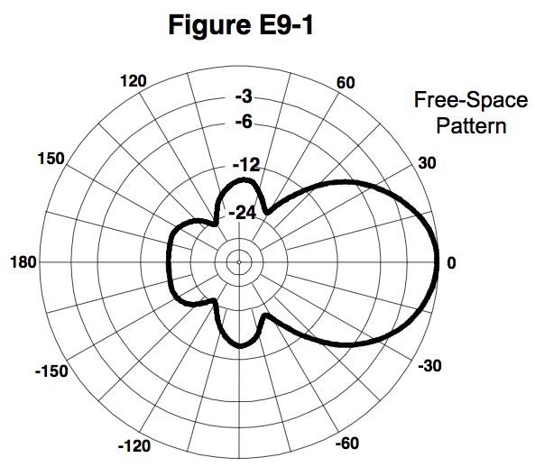
In the antenna radiation pattern shown in Figure E9-1, what is the 3-dB beamwidth?
  • 75 degrees
  • Correct Answer
    50 degrees
  • 25 degrees
  • 30 degrees

The numbers on the outer ring are degrees of a compass. The numbers in the center are in dB of gain. Negative dB of gain are shown on the chart. Positive dB gain are not shown.

Looking at the \(-3 \text{ dB}\) ring (the second largest circle), find the two points where the radiation pattern crosses the ring. The negative point is about \(25^{\circ}\) and the positive is about \(25^{\circ}\); therefore, the beam width is the sum of \(25^{\circ}\) and \(25^{\circ}\) which equals \(50^{\circ}\). - K4AGO

Last edited by wileyj2956. Register to edit

Tags: none

In the antenna radiation pattern shown in Figure E9-1, what is the front-to-back ratio?
  • 36 dB
  • Correct Answer
    18 dB
  • 24 dB
  • 14 dB

Front-to-back ratio is the ratio of power gain between the front and rear lobes of a directional antenna. See Wikipedia.

In this case, the main lobe has \(0 \text{ dB}\) gain and the rear lobe has \(-18 \text{ dB}\) gain. (The rear lobe gain is midway between the \(-12 \text{ dB}\) and \(-24 \text{ dB}\) circles.) Therefore the difference between them is \(18 \text{ dB}\).

Last edited by wileyj2956. Register to edit

Tags: none

In the antenna radiation pattern shown in Figure E9-1, what is the front-to-side ratio?
  • 12 dB
  • Correct Answer
    14 dB
  • 18 dB
  • 24 dB

This is simply a case of taking the difference between the value of the peak front radiation and the peak side radiation. The front is 0dB and the side is less than -12 and more than -24, much nearer the -12 value. So, the front-to-side ratio is greater than 0 - -12dB or 12dB but only a little greater so given the answers shows 14dB looks more likely than 18dB.

A Silly HINT: All distractors are multiples of 6 (12, 18, 24) except for the correct answer, 14

Last edited by crd716. Register to edit

Tags: none

What may occur when a directional antenna is operated at different frequencies within the band for which it was designed?
  • Feed point impedance may become negative
  • The E-field and H-field patterns may reverse
  • Element spacing limits could be exceeded
  • Correct Answer
    The gain may change depending on frequency
This question does not yet have an explanation! Register to add one

Tags: none

What usually occurs if a Yagi antenna is designed solely for maximum forward gain?
  • The front-to-back ratio increases
  • Correct Answer
    The front-to-back ratio decreases
  • The frequency response is widened over the whole frequency band
  • The SWR is reduced

Antenna design parameters are often interrelated. For example, if you increase forward gain, you reduce the beam width.

A high front-to-back ratio is desirable to reduce signal coming out the back of the antenna.

Intuitively, as you increase the forward gain, you also increase the F/B. But only to a point---it turns out that as you maximize forward gain, the F/B actually decreases.

And vice versa. You have to compromise a bit on one, in order to maximize the other.

Last edited by doug kc7dnv. Register to edit

Tags: none

If the boom of a Yagi antenna is lengthened and the elements are properly retuned, what usually occurs?
  • Correct Answer
    The gain increases
  • The SWR decreases
  • The front-to-back ratio increases
  • The gain bandwidth decreases rapidly

The boom on a Yagi antenna is the crossbar that supports the elements (the one that is the length of the antenna). The longer the boom the more gain tha antenna has, assuming that the elements are all properly tuned.

For more information, see wikipedia

Last edited by kd7bbc. Register to edit

Tags: none

How does the total amount of radiation emitted by a directional gain antenna compare with the total amount of radiation emitted from an isotropic antenna, assuming each is driven by the same amount of power?
  • The total amount of radiation from the directional antenna is increased by the gain of the antenna
  • The total amount of radiation from the directional antenna is stronger by its front to back ratio
  • Correct Answer
    They are the same
  • The radiation from the isotropic antenna is 2.15 dB stronger than that from the directional antenna

Total radiation emitted includes all directions. The directional antenna radiates more in a given direction than the isotropic antenna, but when all directions are included they both radiate the same amount.

Last edited by bigkradio. Register to edit

Tags: none

How can the approximate beamwidth in a given plane of a directional antenna be determined?
  • Correct Answer
    Note the two points where the signal strength of the antenna is 3 dB less than maximum and compute the angular difference
  • Measure the ratio of the signal strengths of the radiated power lobes from the front and rear of the antenna
  • Draw two imaginary lines through the ends of the elements and measure the angle between the lines
  • Measure the ratio of the signal strengths of the radiated power lobes from the front and side of the antenna
This question does not yet have an explanation! Register to add one

Tags: none

What type of computer program technique is commonly used for modeling antennas?
  • Graphical analysis
  • Correct Answer
    Method of Moments
  • Mutual impedance analysis
  • Calculus differentiation with respect to physical properties
This question does not yet have an explanation! Register to add one

Tags: none

What is the principle of a Method of Moments analysis?
  • Correct Answer
    A wire is modeled as a series of segments, each having a uniform value of current
  • A wire is modeled as a single sine-wave current generator
  • A wire is modeled as a series of points, each having a distinct location in space
  • A wire is modeled as a series of segments, each having a distinct value of voltage across it
This question does not yet have an explanation! Register to add one

Tags: none

What is a disadvantage of decreasing the number of wire segments in an antenna model below the guideline of 10 segments per half-wavelength?
  • Ground conductivity will not be accurately modeled
  • The resulting design will favor radiation of harmonic energy
  • Correct Answer
    The computed feed point impedance may be incorrect
  • The antenna will become mechanically unstable

First, let's understand why some answers are wrong (the sequence of answers varies by user so referencing the answers by letter is useless):

Ground conductivity - suppose you are modeling a half-wave dipole in free-space, i.e., where no ground is even present: since ground conductivity is not always relevant to antenna modeling, this answer is non-sensical.

Harmonic energy - each model computation is performed at a single frequency and assumes linearity. Since harmonics arise from nonlinearities, this answer is non-sensical.

Mechanical stability - An antenna model that measures wire segment lengths in fractions of a wavelength is inherently an electrical model, not a mechanical model. Therefore, this answer is non-sensical.

Now, let's focus on why feed point impedance is the best answer:

The accuracy of the computed feed point impedance is highly dependent on the accuracy of the computed current at the feed point. Using wire segments that are electrically too long (i.e., too few wire segments per wavelength) will not accurately model the true current, and therefore impedance, at the feed point.

Hint: In this question, you may want to pick the "incorrect" answer (the only question that ends in "incorrect")

Last edited by ki5hav. Register to edit

Tags: none

What is the far-field of an antenna?
  • The region of the ionosphere where radiated power is not refracted
  • The region where radiated power dissipates over a specified time period
  • The region where radiated field strengths are obstructed by objects of reflection
  • Correct Answer
    The region where the shape of the antenna pattern is independent of distance

As the RF energy leaves the antenna, it generally expands into the full beam. However, this expansion only continues for a specific distance. At a certain distance from the antenna, the beam pattern no longer changes but remains relatively constant. This distance is referred to as the far field distance.

The far field radiation pattern is typically what we are most concerned with in radio communication as practically every receiving antenna is going to be in the far field under real conditions.

Hint: Antenna patterns usually have a perverbial shape, only answer with 'shape'

Last edited by comdijital. Register to edit

Tags: none

What does the abbreviation NEC stand for when applied to antenna modeling programs?
  • Next Element Comparison
  • Correct Answer
    Numerical Electromagnetics Code
  • National Electrical Code
  • Numeric Electrical Computation

The Numerical Electromagnetics Code (NEC) is a popular antenna modeling software package for wire and surface antennas. It is credited to Gerald J. Burke and Andrew J. Poggio, and was originally written in FORTRAN in the 1970s. The code was made publicly available for general use and has subsequently been distributed for many computer platforms from mainframes to PCs.

http://en.wikipedia.org/wiki/Numerical_Electromagnetics_Code

Last edited by kd4mdf. Register to edit

Tags: none

What type of information can be obtained by submitting the details of a proposed new antenna to a modeling program?
  • SWR vs. frequency charts
  • Polar plots of the far-field elevation and azimuth patterns
  • Antenna gain
  • Correct Answer
    All of these choices are correct
This question does not yet have an explanation! Register to add one

Tags: none

Go to E9A Go to E9C