Login or Register for FREE!
Subelement E9
ANTENNAS AND TRANSMISSION LINES
Section E9C
Wire and phased vertical antennas: beverage antennas; rhombic antennas; elevation above real ground; ground effects as related to polarization; take-off angles
What is the radiation pattern of two 1/4-wavelength vertical antennas spaced 1/2-wavelength apart and fed 180 degrees out of phase?
  • A cardioid
  • Omnidirectional
  • A figure-8 broadside to the axis of the array
  • Correct Answer
    A figure-8 oriented along the axis of the array

The most significant factors here are that the elements are fed 180 degrees out of phase and are spaced 1/2-wavelength apart. In a half-wavelength a radio frequency signal differs by 180 degrees from the source. So, you can also say that the elements are spaced 180 degrees apart. Therefore, when a signal leaving one element reaches the other it is in phase with the radiation from the element it is reaching and thus the output of each element re-enforces the output from the other.

That means the pattern is essentially two overlapping circular outputs from the two elements and strengthened in the direction away from the antenna in each direction in line with the axis through the two antenna elements. In other words: a figure-8 oriented along the axis of the array.

See also: http://www.bellscb.com/cb_radio_hobby/antennas/antarray.html, last Fig

Memory tips from other users:

  • "180 degrees" has an 8, so it's a figure eight answer. The signal is "O"ut of phase, so the pattern is "O"riented along the axis. Choose the answer with 180 and an "O" word. (See other easily confused similar question, E9C03, whose answer is a broadside figure 8.)

  • Visualize a signal leaving one of the verticals as "slow" when heading off in any direction except through the other phased vertical, but when it leaves the first vertical element and travels "through" the area immediately surrounding the second vertical on its way to its intended target, it gets a little "boost" and speeds up. The "boost" effect is 'along the axis of the array' which, in other words, means when the two antennas are aligned, one in front of the other, on a path toward the intended target.

  • "Half, Opposite, Along" - For 1/2-wavelength apart and 180 degrees out of phase (opposite), think of the figure-8 pattern stretching along the line connecting the two antennas. The word "Half" also visually resembles the figure-8 lying along the axis.

  • "Out of Phase" and "Oriented" both start with the letter "O". Two O's make an 8. So look for "8" and "Oriented"

Last edited by kd7bbc. Register to edit

Tags: none

What is the radiation pattern of two 1/4-wavelength vertical antennas spaced 1/4-wavelength apart and fed 90 degrees out of phase?
  • Correct Answer
    A cardioid
  • A figure-8 end-fire along the axis of the array
  • A figure-8 broadside to the axis of the array
  • Omnidirectional

See Figure 3 at: http://www.bellscb.com/cb_radio_hobby/antennas/antarray.html

Memory Tip: The "9" in 90 degrees looks a bit like a drawing of a cardioid shape.

Mnemonic: "Quarter, Quarter, Heart" - For 1/4-wavelength apart and 90 degrees out of phase, think of a cardioid, which resembles a heart shape. "Quarter, Quarter" for both the spacing and the phase creates an easy-to-remember connection to the cardioid shape.

Silly hack: Think of an index card (for cardoid). The angle of the card is 90 degrees at all corners.

Last edited by sillygoose333. Register to edit

Tags: none

What is the radiation pattern of two 1/4-wavelength vertical antennas spaced 1/2-wavelength apart and fed in phase?
  • Omnidirectional
  • A cardioid
  • Correct Answer
    A Figure-8 broadside to the axis of the array
  • A Figure-8 end-fire along the axis of the array

There are many ways to put up antennas that are directional. One way to get directionality without a tower is to use phased vertical arrays.

In general, the phased vertical array consists of two or more quarter-wave vertical antennas. The radiation pattern that the array will have depends on how you feed the vertical antennas.

So, for example, the radiation pattern of two 1/4-wavelength vertical antennas spaced 1/2-wavelength apart and fed 180 degrees out of phase is a figure-8 oriented along the axis of the array. (E9C01) The radiation pattern of two 1/4-wavelength vertical antennas spaced 1/4-wavelength apart and fed 90 degrees out of phase is a cardioid. (E9C02) The radiation pattern of two 1/4-wavelength vertical antennas spaced 1/2-wavelength apart and fed in phase is a Figure-8 broadside to the axis of the array. (E9C03)

Source kb6nu.com - Extra Class question of the day: Wire and phased vertical antennas


Memory Tips from other users:

  • "In phase" is pretty standard, and a dipole is pretty standard. So the pattern is roughly the same as a dipole: a figure-8 broadside to the antenna.

  • "Half, Same, Broadside" - For 1/2-wavelength apart and in phase (same phase), visualize the figure-8 broadside to the axis. The word "Broadside" helps to remember that the pattern is oriented perpendicular to the line connecting the two antennas.

Last edited by kd7bbc. Register to edit

Tags: none

Which of the following describes a basic unterminated rhombic antenna?
  • Unidirectional; four-sides, each side one quarter-wavelength long; terminated in a resistance equal to its characteristic impedance
  • Correct Answer
    Bidirectional; four-sides, each side one or more wavelengths long; open at the end opposite the transmission line connection
  • Four-sides; an LC network at each corner except for the transmission connection;
  • Four-sides, each of a different physical length

The rhombic antenna is diamond shaped, each side at least one wavelength long, and is good because of simplicity and it's ability to operate over a wide range of frequencies. Takes a Lot of space, though.

Last edited by ke7kto. Register to edit

Tags: none

What are the disadvantages of a terminated rhombic antenna for the HF bands?
  • The antenna has a very narrow operating bandwidth
  • The antenna produces a circularly polarized signal
  • Correct Answer
    The antenna requires a large physical area and 4 separate supports
  • The antenna is more sensitive to man-made static than any other type

They require a huge field and space and supports if you are thinking of putting one of these in your backyard you better have a huge property. Of course there are some that are not spaced that much. Look at the picture. https://www.google.com/search?q=rhombic+antenna&safe=active&um=1&ie=UTF-8&hl=en&tbm=isch&source=og&sa=N&tab=wi&ei=gWPOUKzECcLCyQGx-oCwAQ&biw=1680&bih=949&sei=j2POUNuRCcqSyQH284GoCA

Last edited by minininjaman . Register to edit

Tags: none

What is the effect of a terminating resistor on a rhombic antenna?
  • It reflects the standing waves on the antenna elements back to the transmitter
  • Correct Answer
    It changes the radiation pattern from bidirectional to unidirectional
  • It changes the radiation pattern from horizontal to vertical polarization
  • It decreases the ground loss

Normally, a rhombic antenna is bi-directional along the longer axis; adding a terminating resistor, usually in the 600 ohm range, at the vertex opposite to the feedpoint makes the rhombic unidirectional in the direction from feedpoint to resistor.

Last edited by wileyj2956. Register to edit

Tags: none

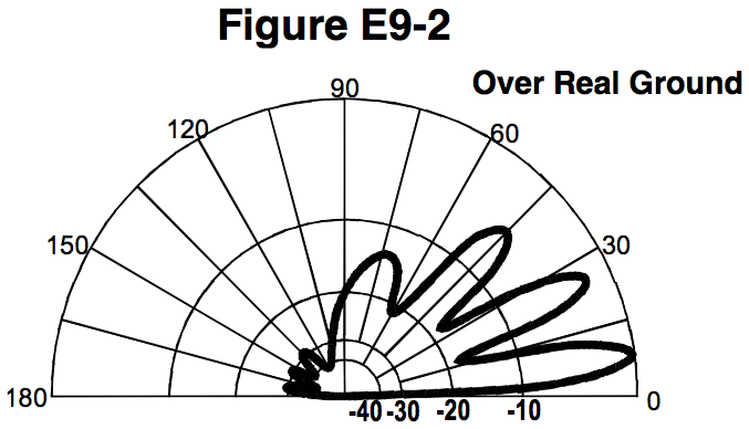
What type of antenna pattern over real ground is shown in Figure E9-2?
  • Correct Answer
    Elevation
  • Azimuth
  • Radiation resistance
  • Polarization
This question does not yet have an explanation! Register to add one

Tags: none

What is the elevation angle of peak response in the antenna radiation pattern shown in Figure E9-2?
  • 45 degrees
  • 75 degrees
  • Correct Answer
    7.5 degrees
  • 25 degrees

Hint: The radiation pattern looks like it's drawn on a protractor. The longest "finger" is the peak response. Starting at 0, it moves up halfway between 0 and 15 degrees at 7.5 degrees. (See the halfway point between 0 and 30?)

Last edited by taco40. Register to edit

Tags: none

What is the front-to-back ratio of the radiation pattern shown in Figure E9-2?
  • 15 dB
  • Correct Answer
    28 dB
  • 3 dB
  • 24 dB

Front-to-Back Ratio applies to directional antennas. It is not generally used in connection with omni-directional antennas (such as verticals) or antennas with symmetrical radiation patterns (such as dipoles). Front-to-Back Ratio is generally defined as the ratio (in dB) of the power emitted in the desired direction (the "front" direction) to that emitted in a direction 180 degrees from the desired direction (the "back" direction. The radiation from an antenna is not usually found concentrated exclusively in a single direction, or even two directions, so a polar plot of radiation versus azimuth will show several "lobes" or regions of strong radiation, with nulls between the lobes.

In the polar radiation plot for this question, the strongest lobe ( which is by default the "front" of the antenna) is at zero dB (outermost curve on the plot). The lobe that is 180 degrees opposite to this strongest lobe is just a bit stronger than the -30 dB curve. Thus, the ratio of the front power to the back power is just under 30 dB or 28 dB as deduced from the multiple choices in the question (nothing else being close). If the lines on the graph were closer together (and the graph larger), it would be possible to read -28 dB directly.

Last edited by ironcal67. Register to edit

Tags: none

How many elevation lobes appear in the forward direction of the antenna radiation pattern shown in Figure E9-2?
  • Correct Answer
    4
  • 3
  • 1
  • 7

Forward direction starts at 0 on the inscribed protractor. This is just a matter of counting lobes at approximately 1) 7.5 degrees, 2) 26 degrees, 3) 45 degrees, and 4) 70 degrees.

Answer: Four (4) elevation lobes.

Last edited by taco40. Register to edit

Tags: none

How is the far-field elevation pattern of a vertically polarized antenna affected by being mounted over seawater versus rocky ground?
  • The low-angle radiation decreases
  • The high-angle radiation increases
  • Both the high- and low-angle radiation decrease
  • Correct Answer
    The low-angle radiation increases

The main effect of placing a vertical antenna over an imperfect ground is that it reduces low-angle radiation. Mounting it over seawater (a very even and highly conductive surface) will increase the low-angle radiation.

Silly Hint: The LARI low angle radiation increase, I (Increase) being different the wrong answer

Last edited by comdijital. Register to edit

Tags: none

When constructing a Beverage antenna, which of the following factors should be included in the design to achieve good performance at the desired frequency?
  • Its overall length must not exceed 1/4 wavelength
  • It must be mounted more than 1 wavelength above ground
  • It should be configured as a four-sided loop
  • Correct Answer
    It should be one or more wavelengths long

According to Wikipedia: "A Beverage consists of a horizontal wire one or two wavelengths long (hundreds of feet at HF to several kilometres for longwave) suspended above the ground, with the feedline to the receiver attached to one end and the other terminated through a resistor to ground."

http://en.wikipedia.org/wiki/Beverage_antenna

Memory Hint: Beverage antennas are receive antennas. When receiving a beverage, you want a receiver (glass) that's at least big enough to hold the the pour (beverage). When receiving RF, you want an antenna at least big enough to hold a wave.

Hint: long question - 'long' in answer

Hint 2: my favorite Beverage is a long drink.

Last edited by stevenvanvooren. Register to edit

Tags: none

What is the main effect of placing a vertical antenna over an imperfect ground?
  • It causes increased SWR
  • It changes the impedance angle of the matching network
  • Correct Answer
    It reduces low-angle radiation
  • It reduces losses in the radiating portion of the antenna
This question does not yet have an explanation! Register to add one

Tags: none

Go to E9B Go to E9D